Any Sonoff device compatible with a clamp on current meter such as STC-013 #3626
Comments
|
That only puts out 1V at 30A, so it would might need an amplifier depending on the load. Or, you could put it into the analog input. The NodeMCU boards have a built-in resistor divider to make full scale 3V3. You would probably want to full-wave rectify the signal and put a capacitor on it to smooth it out. This should give you an indication of the pump being on or not. |
|
The PZEM-004T works well with Tasmota. If you buy the cheap ESP8266 relay board from the internet (the one with the sub-board parallel to the long edge). Flash it with Tasmota. Select Generic and choose PZEM Rx for Tx and PZEM Tx for Rx. You can then connect the PZEM to the pin header between the relay and power terminal blocks. Use a USB charger PSU or a 5V buck to connect to the power and it will be fine. You'll need to install into an adaptable box as there is live AC on the PZEM. The relay on the board won't work by the way. |
|
Thanks for all the advice guys, I’ve got quite a few parts coming from aliexpress now including a nodemcu , wemo d1 mini and I’ve just added a PZEM-004T following your advice. Could you be more specific about the esp board your refering to @pmknowles, Have I already baught it ?? Once again thanks for the help |
|
I use a sonoff basic back to back with the PZEM-004T encased in the box available from itead. https://www.itead.cc/smart-home/sonoff-ip66.html |
|
Ah that’s just perfect, sale on over at aliexpress so Ive already got another 20 sonoff basic’s coming. Now I know I can use a sonoff and simply select the pins I’m much more in my limited knowledge comfort zone Great work thankyou |
|
Picture:
|

|
Looks good and I’ve got some of them boxes spare as well, I’m almost good to go I’m just doing a bit more research now and one thing I’m struggling with is the gpios and where to connect to the sonoff basic, please could you give details of which pins you connected it to, And if you have one plugged in and handy could you be so kind as to post a picture of the configuration layout on tasmota web gui ? I can’t thank you enough for all the help and the great work you have done with tasmota, my entire home automation system is now 90% tasmota I’ve just got a few unreliable z wave door sensors to swap with tasmota and that’s it |
|
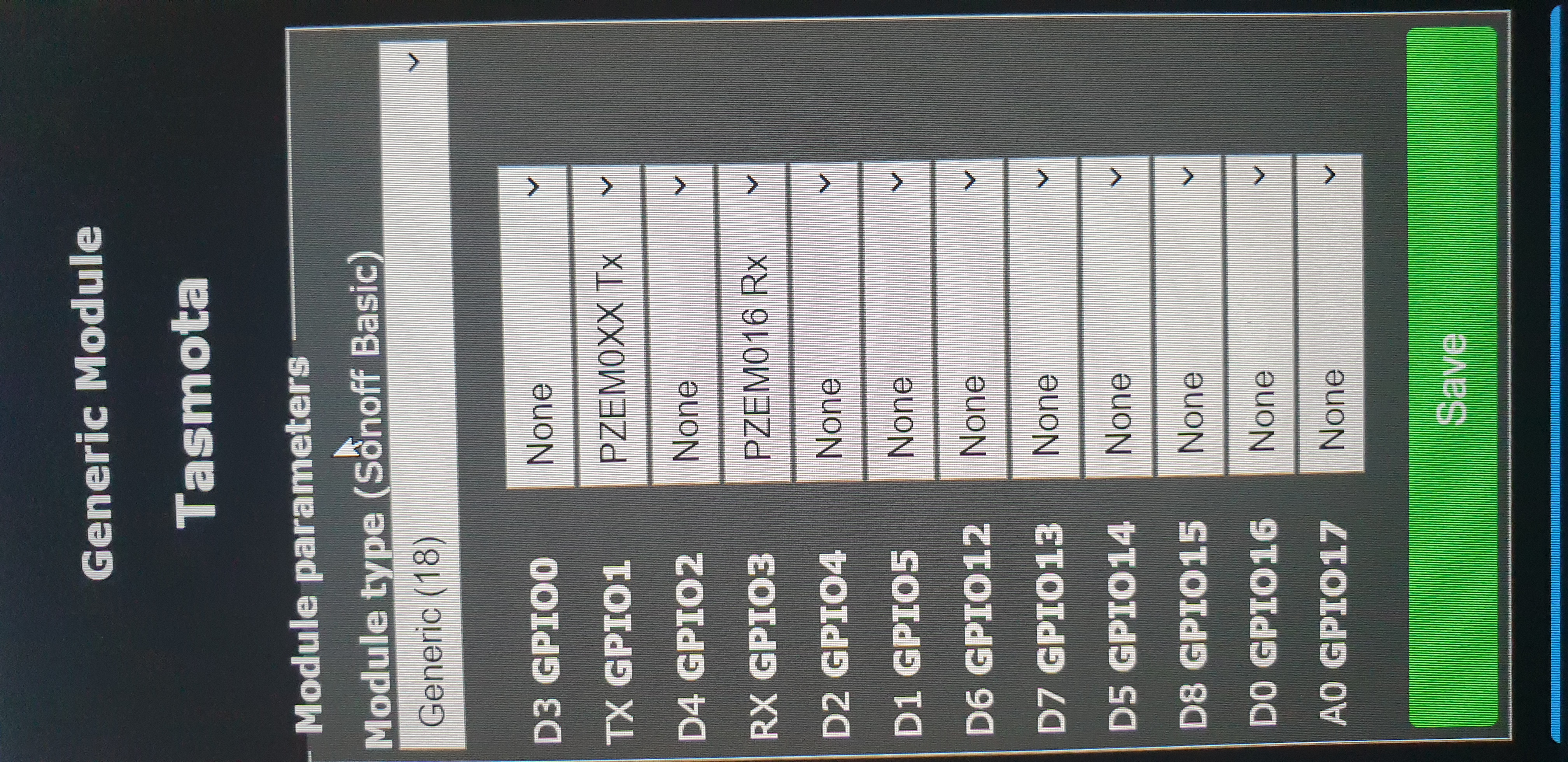
Tasmota config:
I also had to add a 1k resistor to the PZEM-004T to change the serial interface power need from 5V to 3V3.
The four colored wires are then connected to the Sonoff Basic header:
|


|
Absolutely brilliant thankyou, |
|
As I wanted to document this anyway I just made an entry in the wiki https://github.com/arendst/Sonoff-Tasmota/wiki/PZEM004T-Energy-Monitor Feel free to update with your experience once build. |
|
Here’s mine using an HW-655 – it works off 5V and does the 3.3V to 5V on board (the relay is inoperative). It’s mounted in a UK dual gang surface mounted box under the fusebox.
[cid:image003.jpg@01D43F96.2A3E0960]
Sent from Mail<https://go.microsoft.com/fwlink/?LinkId=550986> for Windows 10
…________________________________
From: c3reeman <notifications@github.com>
Sent: Wednesday, August 29, 2018 9:45:38 AM
To: arendst/Sonoff-Tasmota
Cc: pmknowles; Mention
Subject: Re: [arendst/Sonoff-Tasmota] Any Sonoff device compatible with a clamp on current meter such as STC-013 (#3626)
Absolutely brilliant thankyou,
Looking forward to reviving the parts from China !
—
You are receiving this because you were mentioned.
Reply to this email directly, view it on GitHub<#3626 (comment)>, or mute the thread<https://github.com/notifications/unsubscribe-auth/Ajqnsycvy0yEvnkBwMR6miI4BDzfOQhNks5uVlSygaJpZM4WQX43>.
|
|
@arendst what is the difference between what you've built to monitor energy and say the POW or the S31? Is your device limited to a 10A load due to the use of the Sonoff Basic? @pmknowles ditto. Also, other than the 5V input, what is the primary difference between the HW-655 and a Sonoff Basic? Thanks. P.S. Still looking for someone who's used a PZEM to monitor a clothes dryer's energy use that handles the higher amperage. |
|
The PZEM-004T can handle up to 100A (measurement only it can’t switch current)
The HW-655 works at 5V but converts the serial to 3.3V. The PZEM-004T needs 5V on the serial connection (unless you modify with a resistor).
Sent from Mail<https://go.microsoft.com/fwlink/?LinkId=550986> for Windows 10
…________________________________
From: Michael Ingraham <notifications@github.com>
Sent: Wednesday, August 29, 2018 1:31:02 PM
To: arendst/Sonoff-Tasmota
Cc: pmknowles; Mention
Subject: Re: [arendst/Sonoff-Tasmota] Any Sonoff device compatible with a clamp on current meter such as STC-013 (#3626)
@arendst<https://github.com/arendst> what is the difference between what you've built to monitor energy and say the POW or the S31? Is your device limited to a 10A load due to the use of the Sonoff Basic?
@pmknowles<https://github.com/pmknowles> ditto. Also, other than the 5V input, what is the primary difference between the HW-655 and a Sonoff Basic?
Thanks.
P.S. Still looking for someone who's used a PZEM to monitor a clothes dryer's energy use that handles the higher amperage.
—
You are receiving this because you were mentioned.
Reply to this email directly, view it on GitHub<#3626 (comment)>, or mute the thread<https://github.com/notifications/unsubscribe-auth/AjqnsxA-h0y2v-apBKR4WrlIEqjaHq9fks5uVomGgaJpZM4WQX43>.
|
|
The advantage of the PZEM-004T is also that you can connect a load without using a relay. This can be done with a Pow or S31 but then you have to short the relay. In my case it's a complete copy of a Pow as I also use the Basic relay. BTW the energy monitoring of the PZEM-004T looks to me better than the old Pow. |
|
Apologies for high density factor on my part ;-) I THINK I get it now... The Sonoff Basic or HW-655 is powered by appropriate means in order to run the "smarts". The relay on the unit is not (necessarily) used to control the load. In the case of my dryer use case, it would not be used. The PZEM is powered by 5V and hooked up to the load to be monitored, It sends its "readings" via serial interface to the smart switch (Sonoff or HW-655). The the higher power draw is completely handled by the PZEM. Did I get it? Mike |
|
Yep. |
|
In your previous post, since you replied via e-mail, the image you'd sent did not make it into this track. Can you post that photo? Thanks. Mike |
|
|


|
What's the part number on your 5V buck? Does the HW-655 come with the ESP-01 or is it ordered separately? |
|
Here’s the eBay listing
https://www.ebay.co.uk/itm/5Pcs-700mA-AC-DC-5V-3-5W-Buck-Convert-Step-Down-Power-Supply-Module-F-Arduino-M/152339220336?ssPageName=STRK%3AMEBIDX%3AIT&_trksid=p2057872.m2749.l2649
Sent from Mail<https://go.microsoft.com/fwlink/?LinkId=550986> for Windows 10
…________________________________
From: Michael Ingraham <notifications@github.com>
Sent: Wednesday, August 29, 2018 7:09:45 PM
To: arendst/Sonoff-Tasmota
Cc: pmknowles; Mention
Subject: Re: [arendst/Sonoff-Tasmota] Any Sonoff device compatible with a clamp on current meter such as STC-013 (#3626)
@pmknowles<https://github.com/pmknowles> What's the part number on your 5V buck?
—
You are receiving this because you were mentioned.
Reply to this email directly, view it on GitHub<#3626 (comment)>, or mute the thread<https://github.com/notifications/unsubscribe-auth/Ajqnsyt8Z-vOliT0Qz346mKvf0OxQpWEks5uVtjpgaJpZM4WQX43>.
|
|
Generally comes with the ESP-01S - 3rd option in the drop down here. |
|
My HW-655 based PZEM-004T power monitor for my 240V US standard electric clothes dryer. |


Hi - Thanks for the pictures. I am planning to use it for the 220V dryer too.
|
As an aside, take a look at this Shelly device coming mid-March. Rated for 120 amps - more than enough. It would be a much easier way to do this. It would consolidate the three separate modules and reduce a lot of the wiring. Had I not already bought the parts and built mine the week before this was announced (!), I would probably go the Shelly EM route. Mike |
2 questions:
thanks |
|
1- a PZEM is another sensor. See the pictures. You don't need to connect it to any relay if you want. 2- when you select the gpios for the sensor as the tx and rx pins of the esp8266, Tasmota put seriallog to 0 automatically. |
|
Thanks; Just to be clear, can I use 120v from any source to feed the PZEM or does it absolutely have to come from the same circuit I am monitoring? If it doesnt I will build a self contained Box with a 120V power cord+CT clamp and will simply clip it around one of the 120V hots inside the dryer. Would that work? PS: The usb charger would imply an additional external component; would rather use power from the Buck converter. |
|
The input side is essentially a volt and current meter – it is passive. The CT input and AC input are electrically isolated as they are measuring totally different things. I spose you may get some strange readings for apparent power if you’re using different phases.
Regards
Phil K
Sent from Mail<https://go.microsoft.com/fwlink/?LinkId=550986> for Windows 10
From: homeseer666<mailto:notifications@github.com>
Sent: 10 May 2020 21:18
To: arendst/Tasmota<mailto:Tasmota@noreply.github.com>
Cc: pmknowles<mailto:pmknowles@outlook.com>; Mention<mailto:mention@noreply.github.com>
Subject: Re: [arendst/Tasmota] Any Sonoff device compatible with a clamp on current meter such as STC-013 (#3626)
Thanks; Just to be clear, can I use 120v from any source to feed the PZEM or does it absolutely have to come from the same circuit I am monitoring? If it doesnt I will build a self contained Box with a 120V power cord+CT clamp and will simply hook it to one of the 120V hots inside the dryer. Would that work?
PS: The usb charger would imply an additional external component; would rather use power from the Buck converter.
—
You are receiving this because you were mentioned.
Reply to this email directly, view it on GitHub<https://eur04.safelinks.protection.outlook.com/?url=https%3A%2F%2Fgithub.com%2Farendst%2FTasmota%2Fissues%2F3626%23issuecomment-626383645&data=02%7C01%7C%7C87b2f9093b144c0f948708d7f51f57c0%7C84df9e7fe9f640afb435aaaaaaaaaaaa%7C1%7C0%7C637247387263908288&sdata=KQkqTrlMW6Nuahhn9%2BrGvxSkEmzwLsXFBC46JVBk1Xw%3D&reserved=0>, or unsubscribe<https://eur04.safelinks.protection.outlook.com/?url=https%3A%2F%2Fgithub.com%2Fnotifications%2Funsubscribe-auth%2FAI5KPMZ35SC3VVO2ZLWALVTRQ4D2LANCNFSM4FSBPY3Q&data=02%7C01%7C%7C87b2f9093b144c0f948708d7f51f57c0%7C84df9e7fe9f640afb435aaaaaaaaaaaa%7C1%7C0%7C637247387263918280&sdata=XYu8%2Fdpvv7J1Yglugn3yee94zwHszl36p2BXaUjHhnQ%3D&reserved=0>.
|
|
Ok will do some testing when I get the components and report back. |
^^^^^^^ Can confirm that this works perfectly! ^^^^^^It helps a lot, thank you @homeseer666 🙏 note that the 1k resistor looks like this in new SMD boards: #6050 (comment) Also leaving this here, just in case others face the same problem: |


|
Thanks fot the feedback @CarlosGS ! Glad to hear the visual design helped... and worked =) I actually just received (part of) my Aliexpress order from 3 months ago.... Will also test using a separate 120v feed (from the same receptacle as the washer for instance) and just clamp the sensor to one of the phases on the dryer to see if it affects readings. I would prefer this option since I could make the monitoring device self contained with a smaller footprint (vs a bulky 240V bypass box). Easier to switch to another dryer/device if needed. Will report back, cheers |
|
For anyone interested, I finally had time to tackle this project;
Therefore I decided to build the device as a stand alone sensing unit; I tested both designs described above and they work perfectly (HW-655 and Sonoff Basic) thx to @arendst, @pmknowles , @meingraham )
Seems like feeding the PZEM with a separate 120v circuit (vs using one "live" from the "sensed" 240v appliance circuit) wasn't tested above so I can confirm that it is working fine.
The unit is just slighly bigger than a deck of cards so you just mount it to the back of the dryer and run the split core around one of the live wires. As I expected, my dryer has a small service panel so installation was a breeze.
Since north american houses are on split-phase, shown voltage is 120v which reflects one of the 2 live wires used for the split core; however since we are working with split-phase (and not "2" phases https://theengineeringmindset.com/120-240v-split-phase-us-can/) , current should be accurate and you simply need to multiply wattage & energy *2). @meingraham, I guess your results are similar? I'm not 100% sure if apparent/reactive power metrics are ok, but I'm sure some data post processing should resolve any inaccuracies if the data is relevant to you. Not here as I just needed to know if device is off/idle/working.
Hope this helps other North american DIYers. Cheers, |


|
Just built a Sonoff basic version; works equally well with less components;
|

|
Hi Guys, I'm going to go with pmknowles project so I would like to connect the clamp in the fuse box. I pretty much understand all PZEM wiring and what does what however not sure of a few things
Sorry for probably lame questions but I'm not an electrician. I will call for one of to make wiring in the fuse box for sure . Just wanted to know how this should be connected before I call for anyone. Please let me know if you need any clarification of my thoughts as I understand it might not be very clear Anyway its a great project! |
|
Q1. I powered the ESP from the lighting circuit (5A fuse in the UK). I then used an inline 1A fuse from the incoming (100A) breaker to the PZEM.
Q2. The cables are 1.5mm2 but could be any size to match the fuse rating.
Q3. You could use a contactor if you want to switch on/off a higher current remotely – however I’ve replaced 1 PZEM with a Shelly1PM which will switch 16A. I run it in MQTT mode so don’t flash with Tasmota.
Hope that helps
Regards
Phil K
Sent from Mail<https://go.microsoft.com/fwlink/?LinkId=550986> for Windows 10
From: ***@***.***>
Sent: 21 June 2021 19:01
To: ***@***.***>
Cc: ***@***.***>; ***@***.***>
Subject: Re: [arendst/Tasmota] Any Sonoff device compatible with a clamp on current meter such as STC-013 (#3626)
Hi Guys,
I red this thread as I'm going to measure some high voltage devices like cooker, water heater, dryer etc
I'm going to go with pmknowles project so I would like to connect the clamp in the fuse box. I pretty much understand all PZEM wiring and what does what however not sure of a few things
1. Does the PZEM have to be power up with the same fuse/source of the measure device or can it be any source? I thought PZEM can handle up to 100A when using a clamp for measurement. Is it safe to power it up with the line where the load might be 30-40A? I suppose if it is a paraller connection the load is whatever PZEM takes even from the same fuse (FUSE box) ? If it is serial connection (extension lead) the load is whatever measure device takes?
2. On the picture of pmknowles what's the cable size of live wire ? is it 1.5? What would be recommendation here?
3. I also notice some of you use sonoff basic for their project and made like an extension lead to control on/off . I'm I right as by doing it this way you can only use it for load up to 10A as Sonoff basic max load is 10A?
Sorry for probably lame questions but I'm not an electrician. I will call for one of to make wiring in the fuse box for sure . Just wanted to know how this should be connected before I call for anyone.
Please let me know if you need any clarification of my thoughts as I understand it might not be very clear
Anyway its a great project!
Thanks
—
You are receiving this because you were mentioned.
Reply to this email directly, view it on GitHub<https://emea01.safelinks.protection.outlook.com/?url=https%3A%2F%2Fgithub.com%2Farendst%2FTasmota%2Fissues%2F3626%23issuecomment-865235007&data=04%7C01%7C%7C11a1975a108f4df1a7dd08d934dea04a%7C84df9e7fe9f640afb435aaaaaaaaaaaa%7C1%7C0%7C637598953039716583%7CUnknown%7CTWFpbGZsb3d8eyJWIjoiMC4wLjAwMDAiLCJQIjoiV2luMzIiLCJBTiI6Ik1haWwiLCJXVCI6Mn0%3D%7C1000&sdata=JpgawtWYHgoDpkr6Z7C%2BD5D9fn5DzJLKT4FDPRWfGY4%3D&reserved=0>, or unsubscribe<https://emea01.safelinks.protection.outlook.com/?url=https%3A%2F%2Fgithub.com%2Fnotifications%2Funsubscribe-auth%2FAI5KPM7XFY4MDYCRYYGDPKDTT55ANANCNFSM4FSBPY3Q&data=04%7C01%7C%7C11a1975a108f4df1a7dd08d934dea04a%7C84df9e7fe9f640afb435aaaaaaaaaaaa%7C1%7C0%7C637598953039726532%7CUnknown%7CTWFpbGZsb3d8eyJWIjoiMC4wLjAwMDAiLCJQIjoiV2luMzIiLCJBTiI6Ik1haWwiLCJXVCI6Mn0%3D%7C1000&sdata=z6DI2v0hghO1i5tQFLQBd0kR83ViXjrYy3u3wUAfdGE%3D&reserved=0>.
|
|
assuming you are in North america and considering all options: Q1: here not using the same source and so far it works perfectly ; I have 4 units built/deployed (Dryer, Water heater, Hot tub, 240V heater); See design below + above.
Q3: Correct, as per design above, the relay is 10A and can be used as you like. |

|
Q1. I powered the ESP from the lighting circuit (5A fuse in the UK). I then used an inline 1A fuse from the incoming (100A) breaker to the PZEM. I thought you use the same source for both as per your picture via buck for ESP Why did you not use lightning circuit for PZEM as well? Q3. You could use a contactor if you want to switch on/off a higher current remotely – however I’ve replaced 1 PZEM with a Shelly1PM which will switch 16A. I run it in MQTT mode so don’t flash with Tasmota. Hope that helps Regards Phil K I use Sonoffs Pow 2 which also are 16A , they work great for media switching and measurement . To be honest I don't need to switch off the water heater or the dryer, it was only my curiosity :)
I'm in Ireland, 230V single phase for domestic If I'm not wrong
Is the measurement accurate? Forgive me if I write some rubbish's or asking for obvious things. I know very little in this area however I was able to install my Sonoff pows myself so I'm learning :) Thanks for you replies guys |
|
I originally used the same source but the 240V to 5V PSU went after a couple of years so I reconfigured so I didn't need to turn off the whole house electricity to change it in future - of course it hasn't failed since. Bear in mind mine is measuring supply to whole house not just an appliance so my use case may be different.
Accuracy is very good less than 1kWh difference to the meter over a month on average (usage is about 400kWh per month). Typically I change the counters to match the meter once a year and it's around 8- 10 kWh out. I used it to send monthly usage to electricity company using a rule in openHAB but now got a SMETS2 smart meter so it will be retired soon.
Regards
Phil K
Get Outlook for Android<https://aka.ms/AAb9ysg>
…________________________________
From: dajrekt ***@***.***>
Sent: Tuesday, June 22, 2021 12:47:44 AM
To: arendst/Tasmota ***@***.***>
Cc: pmknowles ***@***.***>; Mention ***@***.***>
Subject: Re: [arendst/Tasmota] Any Sonoff device compatible with a clamp on current meter such as STC-013 (#3626)
Q1. I powered the ESP from the lighting circuit (5A fuse in the UK). I then used an inline 1A fuse from the incoming (100A) breaker to the PZEM.
I thought you use the same source for both as per your picture via buck for ESP
Why did you not use lightning circuit for PZEM as well?
Does it need 1A fuse for PZEM?
Would you have any diagram?
Q3. You could use a contactor if you want to switch on/off a higher current remotely – however I’ve replaced 1 PZEM with a Shelly1PM which will switch 16A. I run it in MQTT mode so don’t flash with Tasmota. Hope that helps Regards Phil K
I use Sonoffs Pow 2 which also are 16A , they work great for media switching and measurement . To be honest I don't need to switch off the water heater or the dryer, it was only my curiosity :)
assuming you are in North america and considering all options:
I'm in Ireland, 230V single phase for domestic If I'm not wrong
Q1: here not using the same source and so far it works perfectly ; I have 4 units built/deployed (Dryer, Water heater, Hot tub, 240V heater); See design below + above.
Is the measurement accurate?
I will try it for sure but for some equipment I think will be easier to connect it in the fuse box.
Forgive me if I write some rubbish's or asking for obvious things. I know very little in this area however I was able to install my Sonoff pows myself so I'm learning :)
Thanks for you replies guys
—
You are receiving this because you were mentioned.
Reply to this email directly, view it on GitHub<https://emea01.safelinks.protection.outlook.com/?url=https%3A%2F%2Fgithub.com%2Farendst%2FTasmota%2Fissues%2F3626%23issuecomment-865419642&data=04%7C01%7C%7C42189024c42744e0714c08d9350ef7af%7C84df9e7fe9f640afb435aaaaaaaaaaaa%7C1%7C0%7C637599160657322167%7CUnknown%7CTWFpbGZsb3d8eyJWIjoiMC4wLjAwMDAiLCJQIjoiV2luMzIiLCJBTiI6Ik1haWwiLCJXVCI6Mn0%3D%7C1000&sdata=Xqfq4lCuLvUCTYQbzdG%2BVPKuI9W8xW0%2Bqv0Mw3pOTJs%3D&reserved=0>, or unsubscribe<https://emea01.safelinks.protection.outlook.com/?url=https%3A%2F%2Fgithub.com%2Fnotifications%2Funsubscribe-auth%2FAI5KPM6U7KHWQ4CM7EVUUHLTT7FSBANCNFSM4FSBPY3Q&data=04%7C01%7C%7C42189024c42744e0714c08d9350ef7af%7C84df9e7fe9f640afb435aaaaaaaaaaaa%7C1%7C0%7C637599160657332122%7CUnknown%7CTWFpbGZsb3d8eyJWIjoiMC4wLjAwMDAiLCJQIjoiV2luMzIiLCJBTiI6Ik1haWwiLCJXVCI6Mn0%3D%7C1000&sdata=tgUt8XTYxLJfVUHJFd4mmZa4%2FRVnXtAZjJn8SHY6idk%3D&reserved=0>.
|
|
I used a POW on my 3kW (13A) immersion heater. There was a strange smell one morning and the housing had melted. The POW was still working. It's now in a different housing on the dishwasher. The immersion now has a Shelly1PM with the temperature sensor adaptor.
Regards
Phil K
Get Outlook for Android<https://aka.ms/AAb9ysg>
…________________________________
From: Philip Knowles ***@***.***>
Sent: Tuesday, June 22, 2021 6:00:00 AM
To: arendst/Tasmota ***@***.***>; arendst/Tasmota ***@***.***>
Cc: Mention ***@***.***>
Subject: Re: [arendst/Tasmota] Any Sonoff device compatible with a clamp on current meter such as STC-013 (#3626)
I originally used the same source but the 240V to 5V PSU went after a couple of years so I reconfigured so I didn't need to turn off the whole house electricity to change it in future - of course it hasn't failed since. Bear in mind mine is measuring supply to whole house not just an appliance so my use case may be different.
Accuracy is very good less than 1kWh difference to the meter over a month on average (usage is about 400kWh per month). Typically I change the counters to match the meter once a year and it's around 8- 10 kWh out. I used it to send monthly usage to electricity company using a rule in openHAB but now got a SMETS2 smart meter so it will be retired soon.
Regards
Phil K
Get Outlook for Android<https://aka.ms/AAb9ysg>
________________________________
From: dajrekt ***@***.***>
Sent: Tuesday, June 22, 2021 12:47:44 AM
To: arendst/Tasmota ***@***.***>
Cc: pmknowles ***@***.***>; Mention ***@***.***>
Subject: Re: [arendst/Tasmota] Any Sonoff device compatible with a clamp on current meter such as STC-013 (#3626)
Q1. I powered the ESP from the lighting circuit (5A fuse in the UK). I then used an inline 1A fuse from the incoming (100A) breaker to the PZEM.
I thought you use the same source for both as per your picture via buck for ESP
Why did you not use lightning circuit for PZEM as well?
Does it need 1A fuse for PZEM?
Would you have any diagram?
Q3. You could use a contactor if you want to switch on/off a higher current remotely – however I’ve replaced 1 PZEM with a Shelly1PM which will switch 16A. I run it in MQTT mode so don’t flash with Tasmota. Hope that helps Regards Phil K
I use Sonoffs Pow 2 which also are 16A , they work great for media switching and measurement . To be honest I don't need to switch off the water heater or the dryer, it was only my curiosity :)
assuming you are in North america and considering all options:
I'm in Ireland, 230V single phase for domestic If I'm not wrong
Q1: here not using the same source and so far it works perfectly ; I have 4 units built/deployed (Dryer, Water heater, Hot tub, 240V heater); See design below + above.
Is the measurement accurate?
I will try it for sure but for some equipment I think will be easier to connect it in the fuse box.
Forgive me if I write some rubbish's or asking for obvious things. I know very little in this area however I was able to install my Sonoff pows myself so I'm learning :)
Thanks for you replies guys
—
You are receiving this because you were mentioned.
Reply to this email directly, view it on GitHub<https://emea01.safelinks.protection.outlook.com/?url=https%3A%2F%2Fgithub.com%2Farendst%2FTasmota%2Fissues%2F3626%23issuecomment-865419642&data=04%7C01%7C%7C42189024c42744e0714c08d9350ef7af%7C84df9e7fe9f640afb435aaaaaaaaaaaa%7C1%7C0%7C637599160657322167%7CUnknown%7CTWFpbGZsb3d8eyJWIjoiMC4wLjAwMDAiLCJQIjoiV2luMzIiLCJBTiI6Ik1haWwiLCJXVCI6Mn0%3D%7C1000&sdata=Xqfq4lCuLvUCTYQbzdG%2BVPKuI9W8xW0%2Bqv0Mw3pOTJs%3D&reserved=0>, or unsubscribe<https://emea01.safelinks.protection.outlook.com/?url=https%3A%2F%2Fgithub.com%2Fnotifications%2Funsubscribe-auth%2FAI5KPM6U7KHWQ4CM7EVUUHLTT7FSBANCNFSM4FSBPY3Q&data=04%7C01%7C%7C42189024c42744e0714c08d9350ef7af%7C84df9e7fe9f640afb435aaaaaaaaaaaa%7C1%7C0%7C637599160657332122%7CUnknown%7CTWFpbGZsb3d8eyJWIjoiMC4wLjAwMDAiLCJQIjoiV2luMzIiLCJBTiI6Ik1haWwiLCJXVCI6Mn0%3D%7C1000&sdata=tgUt8XTYxLJfVUHJFd4mmZa4%2FRVnXtAZjJn8SHY6idk%3D&reserved=0>.
|
|
Thanks guys for your input I have another question. Seems I have everything connected and configured but I'm not getting any readings from PZEM. Mine is V3 , someone above mentioned the same. Is there any issue with V3 or is it something wrong with my setup? I checked multiply times how is PZEM connected with hw655 and all looks good to me. 5V-5V , TX-RX, RX-TX , GND- GND. Any idea? ESP shows 0 everywhere . I also replaced HW and PZEM, same thing. Regards |
|
Have you selected PZEM-016 for Rx? Needs to be that for V3 cos RS485.
Regards
Phil K
Get Outlook for Android<https://aka.ms/AAb9ysg>
…________________________________
From: dajrekt ***@***.***>
Sent: Wednesday, June 23, 2021 12:39:52 AM
To: arendst/Tasmota ***@***.***>
Cc: pmknowles ***@***.***>; Mention ***@***.***>
Subject: Re: [arendst/Tasmota] Any Sonoff device compatible with a clamp on current meter such as STC-013 (#3626)
Thanks guys for your input
I have another question. Seems I have everything connected and configured but I'm not getting any readings from PZEM. Mine is V3 , someone above mentioned the same. Is there any issue with V3 or is it something wrong with my setup? I checked multiply times how is PZEM connected with hw655 and all looks good to me. 5V-5V , TX-RX, RX-TX , GND- GND. Any idea? ESP shows 0 everywhere .
Regards
—
You are receiving this because you were mentioned.
Reply to this email directly, view it on GitHub<https://emea01.safelinks.protection.outlook.com/?url=https%3A%2F%2Fgithub.com%2Farendst%2FTasmota%2Fissues%2F3626%23issuecomment-866407134&data=04%7C01%7C%7C40fb13edc44c4639531008d935d708a5%7C84df9e7fe9f640afb435aaaaaaaaaaaa%7C1%7C0%7C637600019939555638%7CUnknown%7CTWFpbGZsb3d8eyJWIjoiMC4wLjAwMDAiLCJQIjoiV2luMzIiLCJBTiI6Ik1haWwiLCJXVCI6Mn0%3D%7C1000&sdata=H7q3eEg4QOx%2BB1kMbwSbcg0mEoXX45K9SySbNeGMT14%3D&reserved=0>, or unsubscribe<https://emea01.safelinks.protection.outlook.com/?url=https%3A%2F%2Fgithub.com%2Fnotifications%2Funsubscribe-auth%2FAI5KPM5V4GJJR3MZAG2GFJDTUENMRANCNFSM4FSBPY3Q&data=04%7C01%7C%7C40fb13edc44c4639531008d935d708a5%7C84df9e7fe9f640afb435aaaaaaaaaaaa%7C1%7C0%7C637600019939565594%7CUnknown%7CTWFpbGZsb3d8eyJWIjoiMC4wLjAwMDAiLCJQIjoiV2luMzIiLCJBTiI6Ik1haWwiLCJXVCI6Mn0%3D%7C1000&sdata=ltY6kqwlwtiXXlCR0lzIitjyrxHNKP3ABU%2Be1kIQn1A%3D&reserved=0>.
|
|
|

I have . but mine is opposite. GPIO1 is RX and GPIO3 is TX and module type is Generic 18 I think. |
Do you mean change it to Sonoff basic? |
is it this one |
thanks, I will check it when I'm back home, Is there a chance that I missed something and the HW-655 must be flashed with something as well? |
|
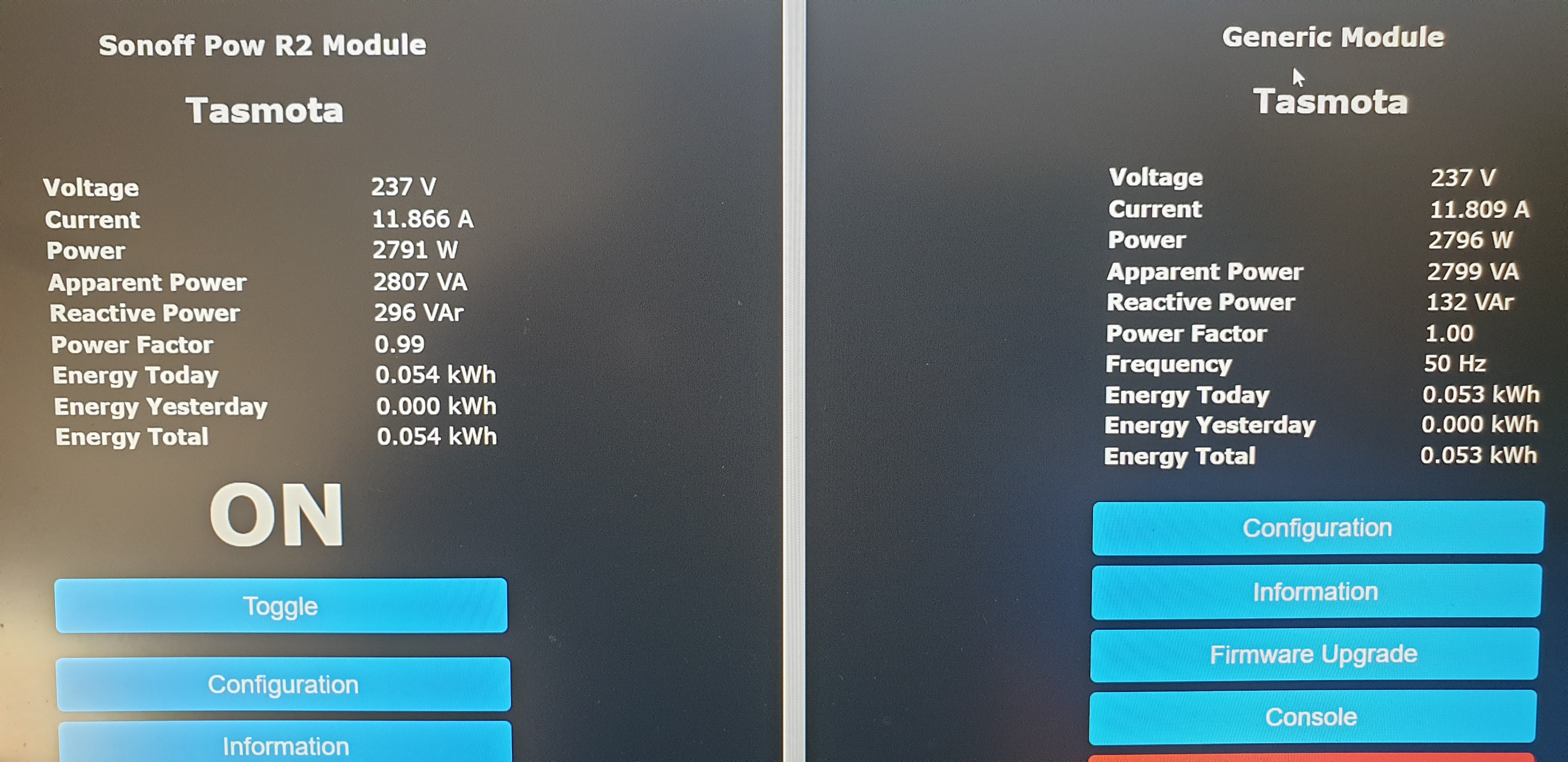
It has started working!
I also set the address of the modbus to 1 with this command in the console This is comparison with Sonoff Pow R2 Now I need to build another two meters and call for electrician to mess with my fuse box :) Thanks for your help! |


|
Additonnal note: If access is easier, you can also use the split cores directly at the breaker box; |
Has anyone used or been able to use a clamp on current meter with any of the sonoff range ?
such as...
https://www.aliexpress.com/item/THGS-YHDC-30A-SCT013-0-100A-Non-invasive-AC-New-Sensor-Split-Core-Current-Transformer-New/32735255457.html?spm=a2g0s.13010208.99999999.272.69863c00L9G8aK
Its intended use is to monitor the current pulled from a cellar sump pump, accuracy isnt important really its just to get an indication of pump on/off. I know the obvious answer to this maybe use a sonoff POW R2, i did this however it failed and the onboard switch went open circuit after only a month of service... so the very thing that was supposed to monitor sump pump failure is the very thing that caused the failure ! A non invasive current monitor would eliminate this happening.
The text was updated successfully, but these errors were encountered: